ASTM F1554 Bolts Price - ASTM A490 A490M Heavy Hex Structural Bolt – Dingshen Metalworks

Short Description:
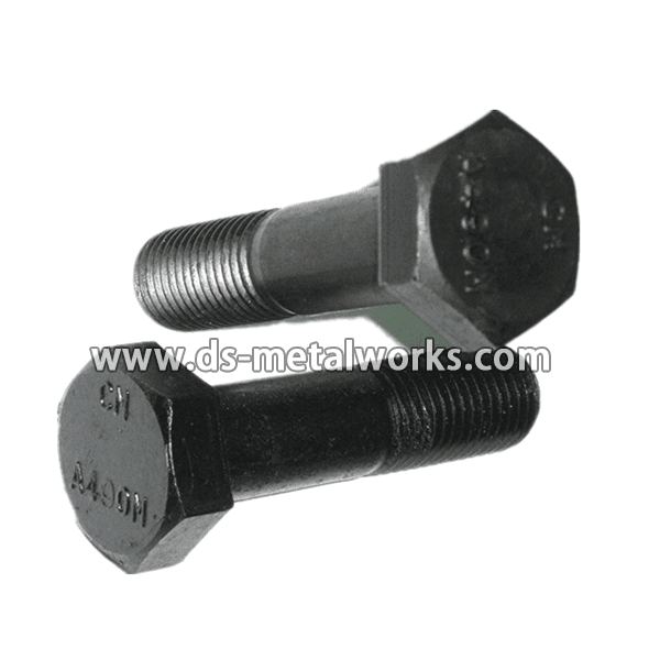
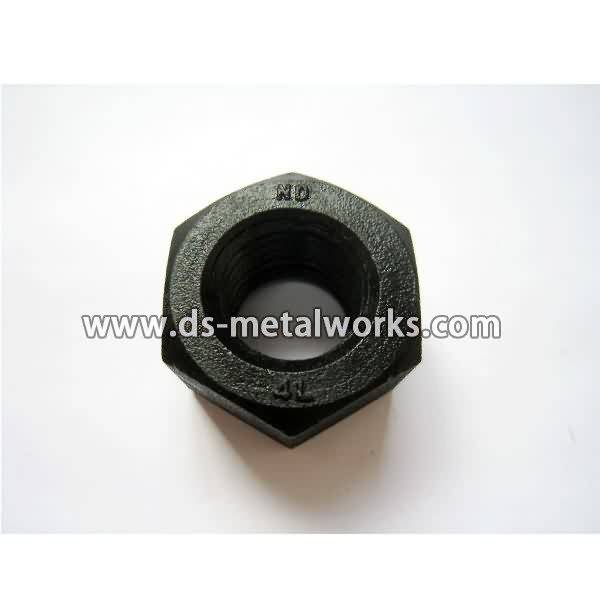
ASTM A490 A490M Heavy Hex Structural Bolts The bolts are intended for use in structural connections. These connections are covered under the requirements of the Specification for Structural Joints Using ASTM A490 Bolts, approved by the Research Council on Structural Connections, endorsed by the American Institute of Steel Construction and by the Industrial Fastener Institute. Dimension: ASME B18.2.6, ASME/ANSI B18.2.3.7M Inch Size: 1/2″-1.1/2″ with various length Metric Size: M1...
Product Detail
Product Tags
ASTM F1554 Bolts Price - ASTM A490 A490M Heavy Hex Structural Bolt – Dingshen Metalworks Detail:
ASTM A490 A490M Heavy Hex Structural Bolts
The bolts are intended for use in structural connections. These connections are covered under the requirements of the Specification for Structural Joints Using ASTM A490 Bolts, approved by the Research Council on Structural Connections, endorsed by the American Institute of Steel Construction and by the Industrial Fastener Institute.
Dimension: ASME B18.2.6, ASME/ANSI B18.2.3.7M
Inch Size: 1/2″-1.1/2″ with various length
Metric Size: M12-M36 with various length
Grade: ASTM A490 A490M Type-1
Finish: Black Oxide, Zinc Plating, Dacromet, and so on
Packing: Bulk about 25 kgs each carton, 36 cartons each pallet
Advantage: High Quality and Strict Quality Control, Competitive price,Timely delivery; Technical support, Supply Test Reports
Please feel free to contact us for more details.
Product detail pictures:


The purchaser fulfillment is our primary focus on. We uphold a consistent level of professionalism, high quality, credibility and service for ASTM F1554 Bolts Price - ASTM A490 A490M Heavy Hex Structural Bolt – Dingshen Metalworks, The product will supply to all over the world, such as: Poland, Durban, Marseille, We'll continue to devote ourselves to market & product development and build a well-knit service to our customer to create a more prosperous future. Please contact us today to find out how we can work together.
Vince Adams and Dean Rose investigate the world of weld prediction and validation in this installment of the Nastran In-CAD webinar series. The webinar focuses on weld terminology, challenges in predicting stress in welds, and common techniques for modeling welds in the FEA environment. Several guidelines are given for outcomes we should expect when modeling welds. After viewing this webinar, the tips and tricks should improve the user’s ability to successfully account for welds in their FEA simulation.
Machine Shop Tool Making, Machining A Finger Plate Clamping Tool – Part 1, by Clickspring.
A Finger Plate clamping tool is a valuable tool in any workshop, and is a great mini mill and mini lathe project. You can also modify the design to suit whatever stock you have in the shop, which means you can finally use some of that scrap you’ve been saving up for that special project.
In this first video of a 2 part series, I build the base for the tool, the cross hole jig, as well as the brass clamping nut. You will see plenty of knurling, lathe turning and milling. Visit the Clickspring website for other mini lathe projects.
Thanks for watching. If you enjoyed the video please give a thumbs up, and leave me a comment. Be sure to check out part 2 of the series.
If you would like to help support the creation of these videos, then head on over to the Clickspring Patreon page: https://www.patreon.com/clickspring
For more info on this tool build, as well as other tool making info, visit the blog site at https://www.clickspringprojects.com
Project Plans available from the Clickspring Store:
https://www.clickspringprojects.com/store.html
Other Videos to Watch:
How To Make A Clock Part 1 – Making The Frames
How To Machine A Small Lathe Carrier
https://youtu.be/zB9XhqzBNJs
Visit the Clickspring Blog:
https://clickspring.weebly.com
Ask Me A Question:
https://www.clickspringprojects.com/contact.html
Follow Clickspring:
https://www.facebook.com/Clickspring1
https://plus.google.com/u/0/113668471124073837794/posts
https://instagram.com/clickspring1/
https://www.tumblr.com/blog/clickspring1
https://twitter.com/clickspring1
https://www.patreon.com/clickspring
Transcript:
00:17 If a small part is too small to be held safely by hand, there’s often no easy way to hold it in a vise either. That’s where this Finger Plate Tool can help. It clamps the workpiece firmly to the tool base, and then the whole thing can either be hand held, or clamped on parallels in a vise.
00:41 Now the dimensions are not very critical, and can be modified to suit whatever stock you have at hand. For example I made my dimensions to suit this rod stock and this piece of scrap steel.
01:05 I roughly trimmed the raw stock for the base, and then squared it up on the mill.
01:25 The hole and groove have to be dead on with each other for the jig to give accurate results. The holes were opened up with a twist drill, and the counterbore for the bushing holder was put in with an end mill.
02:23 I would have liked to have used a double angle cutter to do this, but I don’t have one. So I tilted the work to 45 degrees, and then used a standard end mill.
02:42 I won’t know how successful I was with this,
until the very end when I do some test drilling. The V shape was then roughed out on the band saw. And then the cut was tidied up on the belt sander.
03:44 Next up is this bushing holder, which holds the little bushings to guide the drill for cross holes. The first step is to turn the basic shape on the lathe.
04:25 The center of the part is then drilled out
to the correct size, to accept the cross hole bushings. And then while its still attached to the parent stock, its taken over to the mill to put in that cross hole.
05:14 I wanted this hole to have a good surface
finish, so although I started the hole with a twist drill, I did the final sizing with an end mill. Back on the lathe, a light touch with a file knocks off the burr from the cross hole, and its ready to be parted off.
05:53 The parted surface needs a light facing cut and chamfer to clean it up. And I used a hand chamfering tool to knock the edges off the inside hole. A drop of loctite holds it in place.
07:17 I want this to have a nice knurled finish,
so I made a light pass to make sure the pattern was going down well, and then the knurl was taken to full depth. Once the knurl was complete, the excess was trimmed away, and the tapered profile of the part was formed.
08:49 Thats about half of the work for the tool
completed. In the next video, I’ll finish off the tool by making the lifting screw,the drilling jig bushings and the clamping finger.
References:
Finger Plate Clamping Tool books and plans (let me know if you are aware of any others):
“Workshop Practice Series Number 31″ Stan Bray
https://www.teepublishing.co.uk/books/workshop-practice-series/
“Tools For The Clockmaker And Repairer” John Wilding
https://www.ritetimepublishing.com/
“The Model Engineers Workshop Manual” George H Thomas
https://www.teepublishing.co.uk/books/in-your-workshop/model-engineers-workshop-manual/
“Model Engineer Magazine” Edition Vol 104, Issue 2596, 1951 Commander W.T. Barker
https://www.itech.net.au/modelengineer/
“The Machinist’s Bedside Reader” Guy Lautard
pages 88-91
Machine Shop Tool Making, Machining A Finger Plate Clamping Tool – Part 1


